
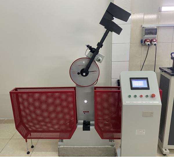
Impact testing machine
The pendulum impact tester in our laboratory; scroll to follow the test step by step.
Specimen in place, hammer latched
The V-notched specimen (10 × 10 × 55 mm) rests against the anvils, notch facing away from the striker.
Pendulum released
The hammer swings down under its own weight and strikes the specimen at the lowest point.
Fracture at the notch
The crack starts at the notch root; the two halves fly out between the anvils.
Absorbed energy is read
The hammer rises less on the far side; the height difference is the energy absorbed by the specimen.
It is a test method to determine the ductile and brittle behavior of materials. The fracture energies of the materials change with the temperature. The breaking energy decreases as the temperature decreases. By making the fracture energy at different temperatures, the transition temperature of the material is determined. This determined value is the temperature at which the material transitions from ductile to brittle fracture. This point is generally defined as the temperature at the point where 50% brittle 50% ductile fracture occurs in the material.